Cutting Speed Chart Pdf

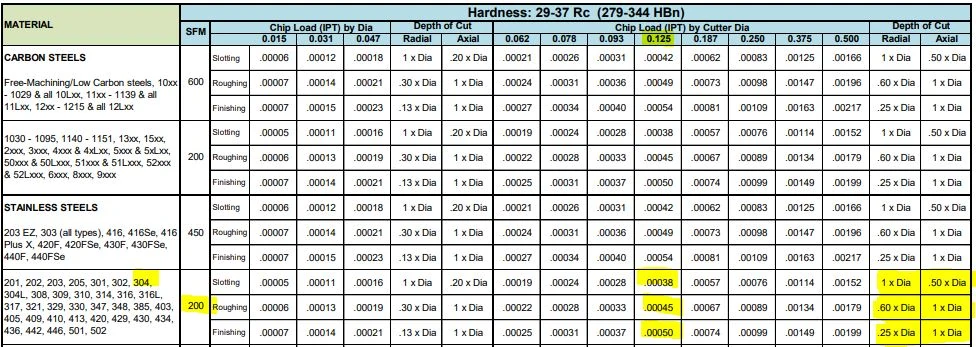
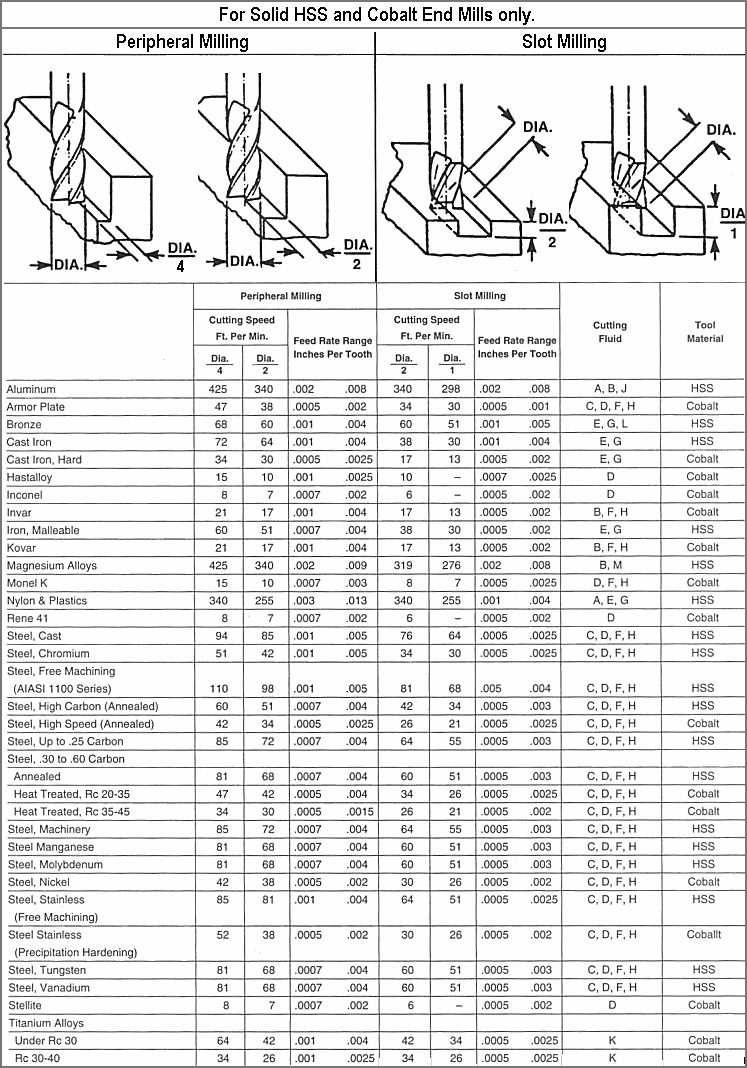
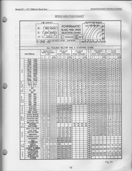
The chart is based on mild steel to the hardest tool steel milling applications.
Cutting speed chart pdf. You can easily break a cutter this way. Then decrease speed by 10. The endmill is being pushed too fast into the cut and the chips get too big.
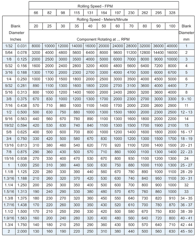
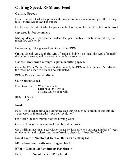
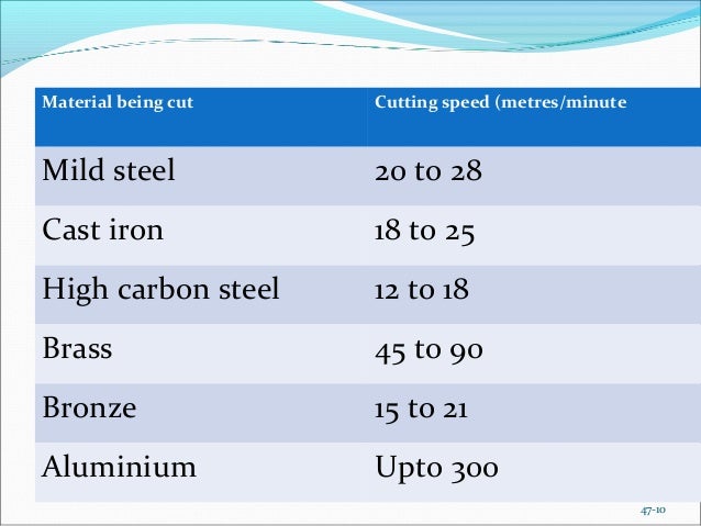
Start off using an rpm derived for the chip load for the material being cut see charts. Start off using an rpm derived for the chip load for the material you are cutting see charts. Choose the average value for sfm and the lower value for feed in the range.
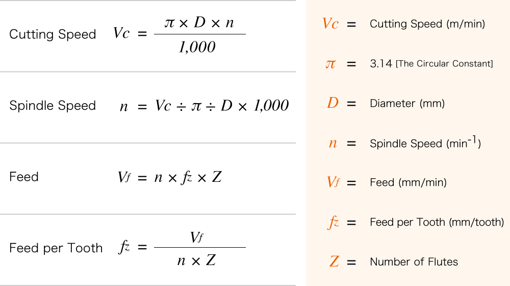
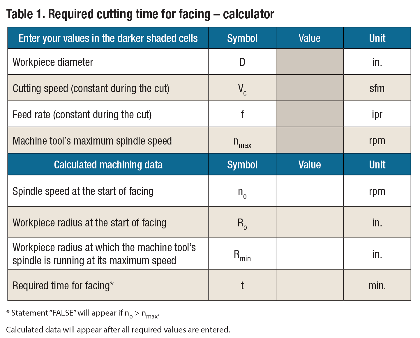
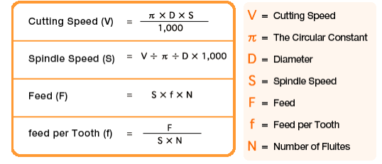
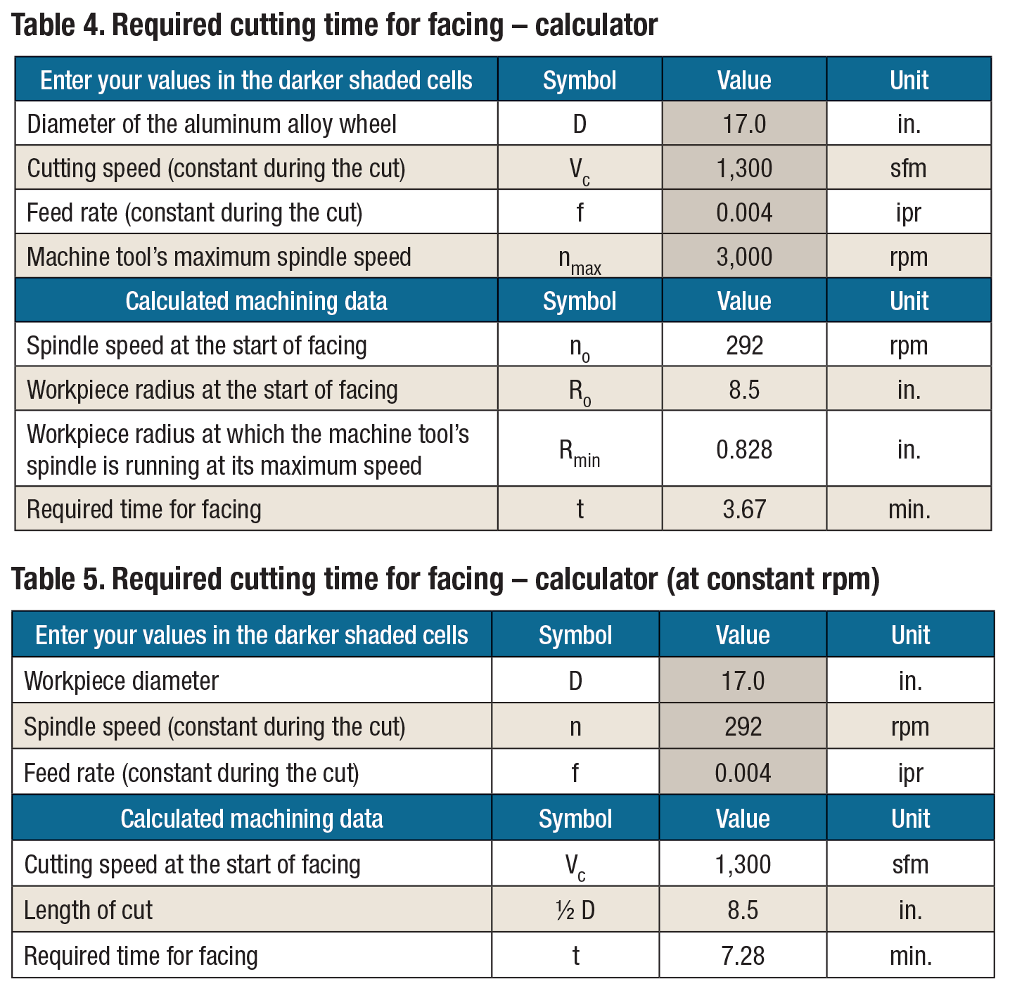
Spindle speed is not the cutting speed. C cutting speed m min n spindle speed rev min f feed per rev mm rev a p axial depth of cut mm d workpiece diameter mm. Compute the dw in order to compute the rpm value of the spindle it is necessary to determine the dw which is the effective engaged tool.
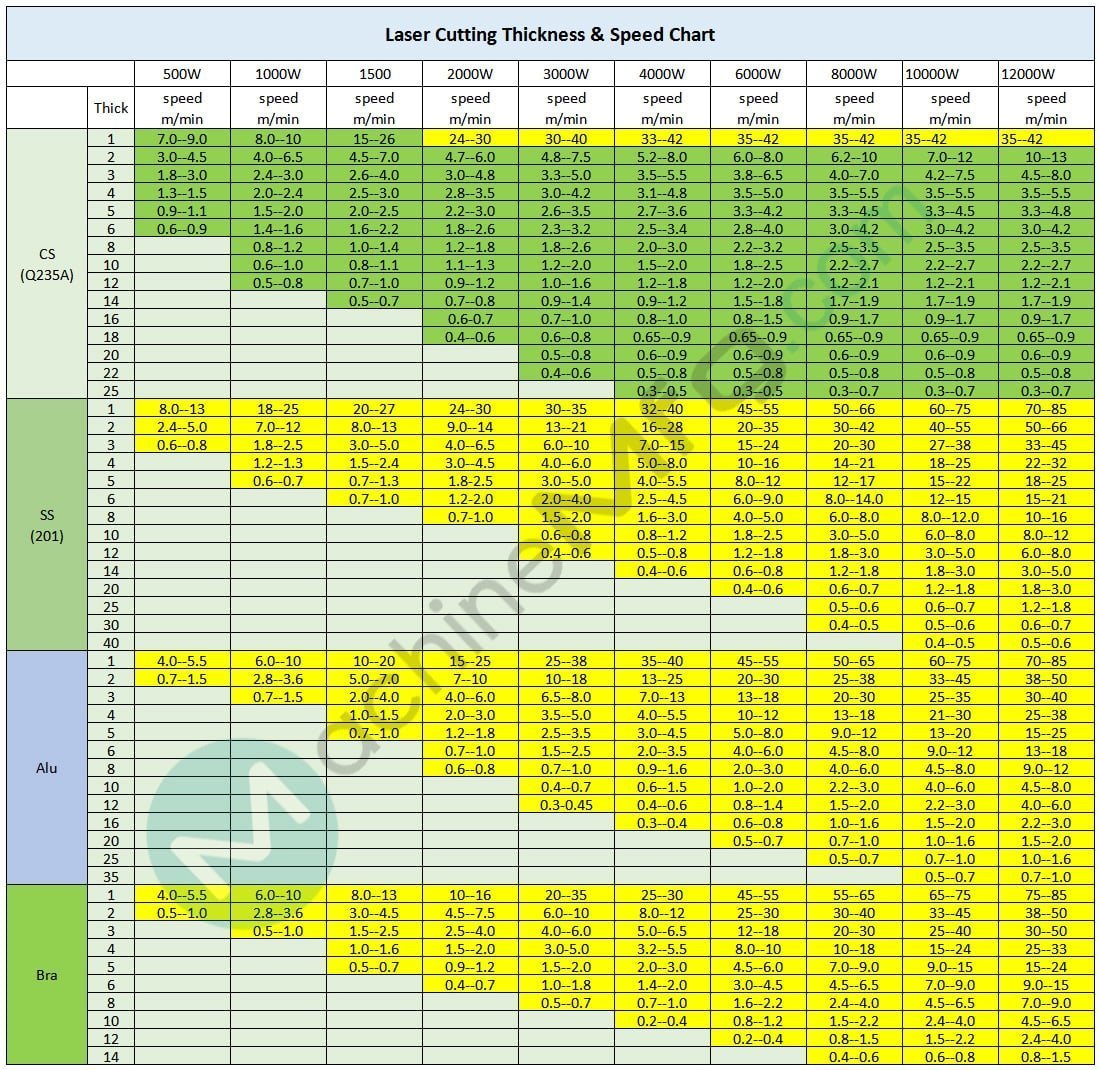
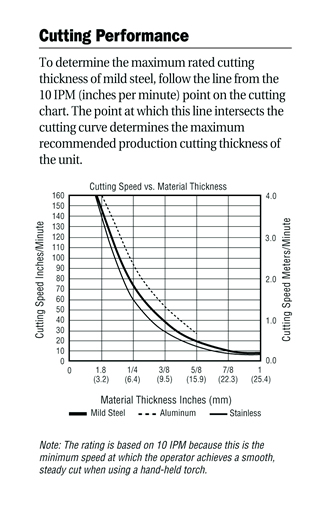
Cutting parameters cutting speed feed 1. Cutting speed recommendations. Cut charts the following cut charts show the consumable parts cutting speeds and the gas and torch settings required for each process.
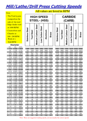
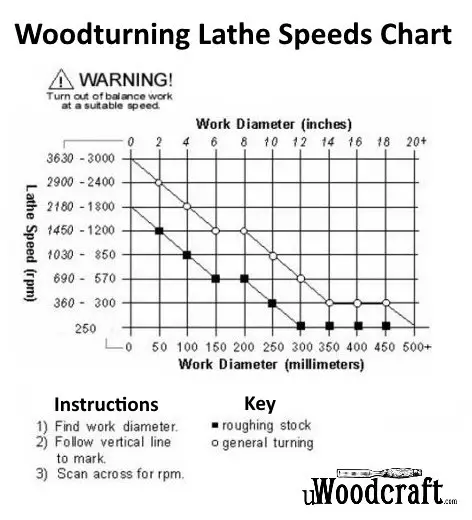
Surface feet per min sfm steel structural 40 60. Drill press speed chart recommended operating speeds rpm accessory softwood pine hardwood hard maple acrylic brass aluminum steel shop notes twist drill bits 3000 3000 1500 750 3000 1500 750 500 2500 2000 1500 nr 3000 1200 750 400 3000 2500 1500 1000 3000 1000 600 350 lubricate drill with oil when cutting steel 1 8 or thicker. If you reduce your spindle speed too much relative to the feedrate you re forcing the flutes of your cutter to take of too much material.
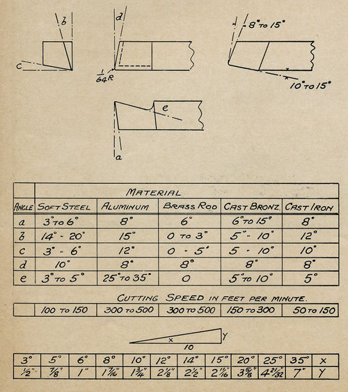
The column of the milling chart list the brinell hardness material condition and the sfpm for hss and carbide tools. Spindle rpm sfm dia. Increase the cutting speed feed rate until the quality of the part s finish starts to decrease or the part is starting to move from hold downs.
Find the cutting speed feed fn find sfm and fn range in table 1 or table 2 at left. If you reduce your feedrate too much relative to spindle speed you will soon. Increase the cutting speed feed rate until the quality of the part s finish starts to decrease or the part is starting to move from hold downs.
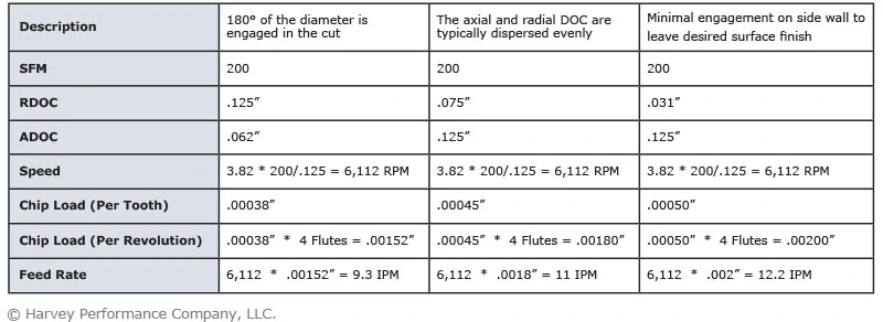
See in the chart below which correction factor c. X 3 82 x tooling correction factor. Corresponds to and multiply the chosen feed in the table for slot milling with this.
Divide the cutter diameter with the radial depth of cut.


